The end goal of this project is to use an STM32 chip to generate and toggle a PWM signal and LED simultaneously, but at different rates. This project will guide you through the step-by-step process of creating a project in CubeMX, assigning pinout, generating PWM, and using concurrent scheduling using FreeRTOS.
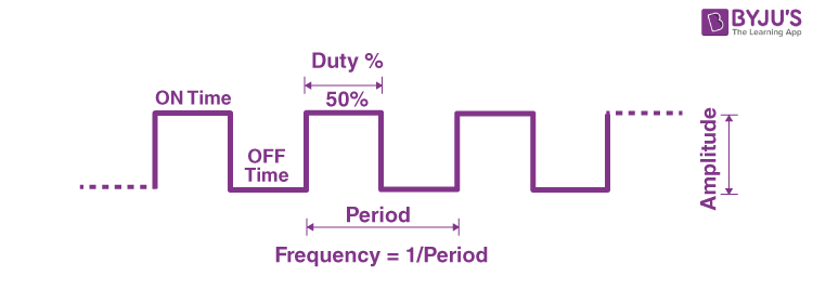
A PWM (Pulse Width Modulation) signal is a simple digital signal often used to emulate an analog signal or control motors and servos. It works by rapidly switching the signal on and off so that the average voltage matches the desired analog value. Here are some key terms to understand when discussing PWM signals:
- Period: The duration of one complete cycle of the signal.
- Duty Cycle: The percentage of one period in which the signal is "on." For example, a PWM signal with a 25% duty cycle is "on" 25% of the time and "off" 75% of the time.
- Resolution: The number of discrete steps in the PWM signal. For example, an 8-bit resolution PWM can have 256 different duty cycle levels (2^8).
The embedded processor we use has a single core, so we will use an operating system (FreeRTOS) to manage priorities and execute multiple tasks simultaneously. These tasks may include sending motor instructions over CAN or handling drivetrain calculations. The switching and execution of tasks happens so quickly that it effectively functions like a concurrent system.

- A laptop, (either MacOS or Windows) with a usb port.
- Basic knowledge of C
- Completed Introduction to Embedded 1
In order to complete this project you will need to download the following software:
-
CubeMX - Used to configure STM32 microcontrollers and generate initialization code. Download the appropriate version from here. It may ask you to create an ST account, so just use your school email.
-
You will also need all of same tools used in the last project.
-
Clone the repository using the following command in your terminal:
git clone https://github.com/RoboMaster-Club/Onboarding-Project-2.git
- Open CubeMX and locate the "Home" screen. It may ask you to create an account first.
- Open the "Create from Board" menu and search for the NUCLEO-L432KC board in the "Commercial Part Number" menu.
- Double-click the correct board to generate the CubeMX project. When it asks if you want to initialize the board to its default mode, press "No" so that the board will be in a clean state. You should see the following if you completed the steps correctly:

- Click on the "Project Manager" tab.
- Name your project
Onboarding_Project_2. - Set the project location to the parent folder of your cloned repository. For example, if your clone is located at
Clones/Onboarding_Project_2, select the parent folderClonesas the project location. - In the "Application Structure" dropdown, select "Basic".
- From the "Toolchain/IDE" dropdown, select "Makefile".
- Name your project

- Return to the "Pinout & Configuration" tab. Open the "Middlewares and Software Packs" menu from the sidebar on the left. Everything should be greyed out except for "FATFS" and "FREERTOS". Click on "FREERTOS".
- In the "Interface" dropdown, select "CMSIS_V2".
- Click on the "Timers" section on the left side of the "Pinout and Configuration" toolbar.
- Click on "TIM1" as this will be used to generate the PWM signal.
- In the new menu that opens, find "Channel 1" and select "PWM Generation CH1" from the dropdown.
- You should see the "PA8" pin turn green in the Pinout view, indicating that it has been successfully enabled.
- In the Configuration menu, open the "Counter Settings" and "PWM Generation Channel 1" menus. Configure them according to the following images:


- Here are a few key settings to understand:
- Prescaler ->
0(each tick of the clock corresponds to one tick of the timer). - Counter mode ->
Up(the timer counts up from 0). - Counter Period ->
255(8-bit resolution signal). - Auto-reload preload ->
Enable(resets the counter when it hits the maximum period). - Pulse ->
127(50% duty cycle). - CH Polarity ->
High(sets the channel output to high when active).
- Prescaler ->
- Hit the blue "Generate Code" button in the top right. It will give you a warning but ignore it for now.
- Open your generated project using VSCode. If you did everything correctly, you should see the following file structure:

- Edit the
Makefilefile and add the following lines to the very end (after where it says# *** EOF ***):

ECHO_WARNING=echo "\033[33m[Warning]\033[0m"
ECHO_SUCCESS=echo "\033[32m[Success]\033[0m"
flash: $(BUILD_DIR)/$(TARGET).bin
	@$(ECHO_WARNING) "Flashing the binary to the board"
	@openocd -f board/st_nucleo_l4.cfg -c "init; reset halt; \
	flash write_image erase $(BUILD_DIR)/$(TARGET).bin 0x08000000; reset run; shutdown"
	@$(ECHO_SUCCESS) "Flashing Complete"
- Test that everything works as expected by running the build task. You should see a new
build/folder appear once it finishes.
- Open the
main.cfile located inSrc/. - Create a function prototype under the comment on line 63 that says
USER CODE BEGIN PFPby adding the following line:
void Toggle_LED(void *pvParameters);
*pvParametersis a pointer to any data you want to pass to a FreeRTOS task. In this case, we will simply passNULL.
- We will create the FreeRTOS Task by using
xTaskCreate()on line 130 under the comment that saysUSER CODE BEGIN RTOS_THREADS.
xTaskCreate(Toggle_LED, "Toggle_LED", 128, NULL, 1, NULL);
- Finally, we will define the function outside of
main()(which ends around line 154).
void Toggle_LED(void *pvParameters)
{
	while (1)
	{
		HAL_GPIO_TogglePin(GPIOB, GPIO_PIN_3);
		osDelay(1000);
	}
}
- In this function, we define an infinite loop where we call the
HAL_GPIO_TogglePin()function to toggle GPIO Pin B3, then useosDelay()to wait 1000ms before the loop repeats. This is very similar to the function you wrote in the last project which can be found here.
- Next, you will repeat the process of steps 2-4 (create function prototype, task, define function) with the function given below:
void Toggle_PWM(void *pvParameters)
{
	static uint8_t on = 0;
	while (1)
	{
		on ^= 1;
		if (on)
		{
			HAL_TIM_PWM_Start(&htim1, TIM_CHANNEL_1);
		}
		else
		{
			HAL_TIM_PWM_Stop(&htim1, TIM_CHANNEL_1);
		}
		osDelay(500);
	}
}
static uint8_t on = 0;defines an unsigned 8-bit integer which keeps its value between function is calls.on ^= 1;uses XOR operator to toggle theonvariable between 1 and 0.HAL_TIM_PWM_Start()andHAL_TIM_PWM_Stop()start/stops the PWM generation on TIM1 CH1 (using the settings we configured in CubeMX in Part 4).
When you have completed all the previous parts, come to a meeting where we will provide you with a board and an additional LED to test your code. You will follow the same procedure from the last project. Both LEDs should blink simultaneously, with the external LED blinking at twice the rate of the green one.