grbl Mega 5X pinout
As defined in cpu_map.h :
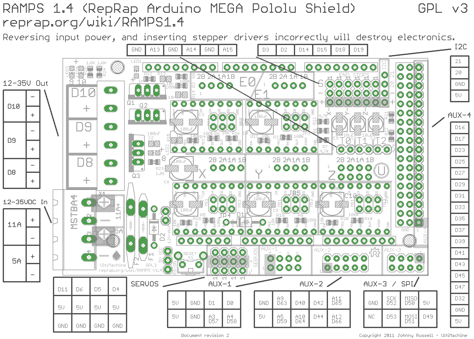
- X, Y & Z motors are in their standard place of the RAMPS shield board,
Axis number Program index Default axis name Step pin Direction pin Disable pin 1 axis[0] X A0 A1 D38 2 axis[1] Y A6 A7 A2 3 axis[2] Z D46 D48 A8 4 axis[3] A D26 D28 D24 5 axis[4] B D36 D34 D30 6 axis[5] C D49 D51 D53 - Axis 4 (default to A) motor is at the E0 place and axis 5 (default to B) motor is at the E1 place,
- Spindle enable is on D4
- Spindle direction is on D5
- Spindle PWM is on D8 (0-12v on RAMPS by default), it can be moved to D6 or D11 (0-5v) by editing config.h
- Coolant mist is on D9
- Coolant flood is on D10
- There is 4 digital output controlled by tht M62 to M65 GCode commands on D16, D17, D23 and D25
- X, Y & Z end stops for min and max are in their standard place too,
- Axis 4 & 5 end stops are on those pins on Aux-2,
- Axis 4 min end stop is on D42,
- Axis 4 max end stop is on D40,
- Axis 5 min end stop is on D44,
- Axis 5 max end stop is on D59,
- Probe switch or sensor is on A15,
- Reset switch (soft reset) is on A9,
- Feed hold switch is on A10,
- Cycle start switch is on A11,
- Safety door switch is on A12,
Location of ports on RAMPS by their name is here : Arduinomega1-4connectors.png
See also the ATmega2560-Arduino pin mapping.
